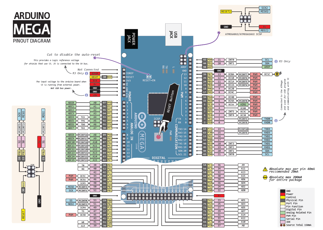
Typically used to add a reset button to shields which block the one on the board. Bring this line LOW to reset the microcontroller. There are a couple of other pins on the board:ĪREF. When an Arduinos pin is configured as a digital output, the pins voltage can be programmatically set to GND or VCC value.
ARDUINO PINOUT SERIAL
By default they measure from ground to 5 volts, though is it possible to change the upper end of their range using the AREF pin and analogReference() function. Arduino Mega 2560 has 54 digital input/output pins, where 16 pins are analog inputs, 14 are PWM pins, and 6 are hardware serial ports (UARTs). The Mega2560 has 16 analog inputs, each of which provide 10 bits of resolution (i.e. pinMode, digitalRead, and digitalWrite functions work as usual, so to read. However, Arduino is unbeatable in this segment due. Note that these pins are not in the same location as the TWI pins on the Duemilanove or Diecimila. Pin numbers in the Arduino IDE correspond directly to the ESP8266 GPIO pin numbers. STM32 Nucleo boards allow anyone to try out new ideas and to quickly create prototypes with any STM32 MCU. Support TWI communication using the Wire library.

about using an LCD character display with Arduino, such as, LCD pinout.
ARDUINO PINOUT HOW TO
When the pin is HIGH value, the LED is on, when the pin is LOW, it’s off. In this Arduino LCD Tutorial we will learn how to connect an LCD (Liquid Crystal. There is a built-in LED connected to digital pin 13. As Arduino Nano is also based on ATmega328P Microcontroller, the technical specifications are similar to that of UNO. Technical Specifications of Arduino Nano. Regarding the pin, I will discuss about them in the Arduino Nano Pinout Section. Arduino UNO is a microcontroller board based on the ATmega328P. The SPI pins are also broken out on the ICSP header, which is physically compatible with the Uno, Duemilanove and Diecimila. Apart from that, the layout of Arduino Nano is very much self-explanatory. These pins support SPI communication using the SPI library. Provide 8-bit PWM output with the analogWrite() function. See the attachInterrupt() function for details. The pins are labeled with a digital number. The microcontroller has 14 pins, each of which can be configured as an input or output. The circuit diagram of the Arduino board is shown below.
ARDUINO PINOUT PRO
These pins can be configured to trigger an interrupt on a low value, a rising or falling edge, or a change in value. Arduino Pro Mini Pinout and Circuit Diagram. Pins 0 and 1 are also connected to the corresponding pins of the ATmega16U2 USB-to-TTL Serial chip.Įxternal Interrupts: 2 (interrupt 0), 3 (interrupt 1), 18 (interrupt 5), 19 (interrupt 4), 20 (interrupt 3), and 21 (interrupt 2). Used to receive (RX) and transmit (TX) TTL serial data. In addition, some pins have specialized functions: Each pin can provide or receive a maximum of 40 mA and has an internal pull-up resistor (disconnected by default) of 20-50 kOhms.

Each of the 54 digital pins on the Arduino 2560 Mega can be used as an input or output, using pinMode(), digitalWrite(), and digitalRead() functions.


 0 kommentar(er)
